 409-842-4404
 Pipe Bevel Angles Explained: 37.5°, J-Bevel & More
Key Takeaways
- The standard bevel for ASME B16.25 process piping is 37.5° (±2.5°) with a 1.6 mm root face. Line pipe is typically 30° (+5°/−0°) under API 5L, welded to API 1104.
- A 37.5° bevel makes a 75° included angle. A 30° bevel makes a 60° included angle.
- V-bevels get expensive on heavy wall because the groove widens fast. ASME B16.25 moves to a compound bevel above 22 mm (0.88 in.).
- A J-bevel (U-groove) cuts weld metal and arc time by about 30 to 50 percent on thick-wall pipe.
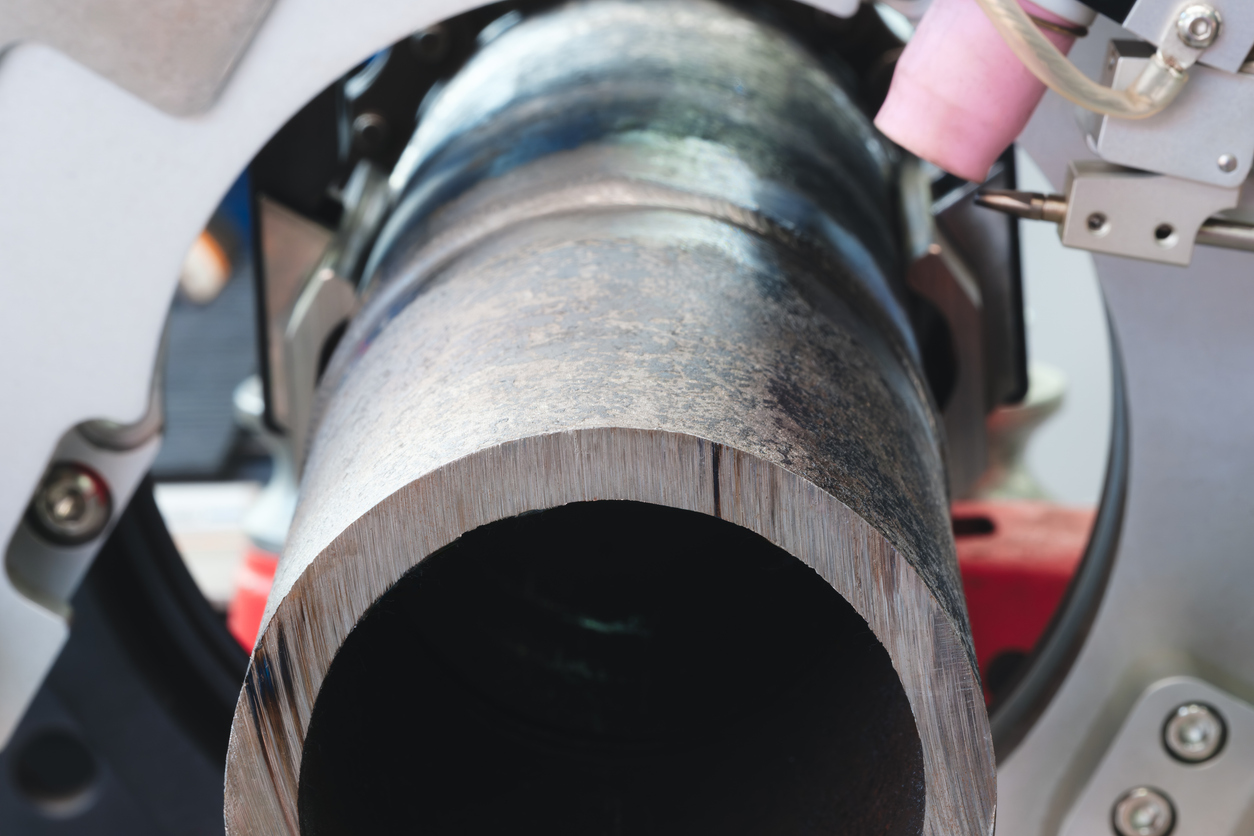
- Precise J-bevels need rigid, stationary machines like the MSI C8H, since hand tools and light clamshells cannot hold the radius.
Pipe bevel angles, explained
The standard pipe bevel angle is 37.5 degrees per ASME B16.25, the spec that governs butt-weld end prep for process and plant piping. Cross-country line pipe is usually beveled at 30 degrees instead. Knowing the right angle for your code is the baseline for passing inspection.
Simply knowing the code is not enough, though. As more projects move to heavy-wall pipe for higher pressures, a standard V-bevel starts to waste filler metal fast, because the groove gets wider and wider at the top as the wall gets thicker.
Switching to a J-bevel can cut weld metal and arc time by up to 50 percent on thick wall. Here is how the angles, tolerances, codes, and tooling fit together.
What is a pipe bevel angle?
A pipe bevel angle is the angle between the prepared edge of the pipe and a line square across the pipe end. Cosmetic chamfering just breaks a sharp edge for safety or handling. A weld prep is an engineered joint shape that controls penetration, heat input, and strength.
Before you set up a weld, a few terms matter, and getting them wrong leads straight to defects and failed X-rays:
- Bevel angle: the angle ground or machined on each pipe end.
- Included angle: the total angle when two beveled ends meet. Two 37.5-degree bevels make a 75-degree included angle.
- Root face (land): the flat, unbeveled strip at the inside edge. It gives the root pass material to fuse into without burning through.
- Root opening (gap): the small space left between the two root faces so the arc can reach the full depth of the joint.
What is the standard pipe bevel angle?
For most pipe welding, the standard bevel angle is 37.5 degrees per side, which forms that 75-degree included angle. ASME B16.25 sets this for standard wall thickness, with a tolerance of plus or minus 2.5 degrees and a root face of 1.6 mm (plus or minus 0.8 mm).
The angle is a balance. Cut it too narrow and the arc cannot reach the root, so you get lack of fusion. Cut it too wide and you waste filler metal and add heat, which can hurt the properties of the base metal.
That is why the tolerance is tight. In automated orbital welding, even a few degrees off can throw off preset deposition rates and leave you with underfill or too much crown.
Bevel angles by code: ASME B16.25 vs. API
End prep follows the application and the governing code, and shop piping and pipelines do not play by the same rules.
For shops, refineries, and power plants, ASME B16.25 governs butt-weld ends. It holds the 37.5-degree bevel for standard walls and gives detailed root-face and transition dimensions, including how to join pipes of different thickness. It is built around the structural reliability of high-pressure process piping.
Cross-country pipelines run differently. Line pipe is typically supplied with a 30-degree bevel (commonly toleranced at plus 5, minus 0 degrees under API 5L), which gives a 60-degree included angle. That narrower groove suits the high-speed, multi-pass field welding that pipelines need, and the welding itself is qualified under API 1104. The smaller angle uses less weld metal per joint while still allowing full penetration.
When to switch from a V-bevel to a J-bevel
A standard V-bevel stops making financial sense as the wall gets thicker. Because a V opens at a constant angle, the groove gets wider and wider at the top as the wall grows.
On heavy-wall pipe (roughly Schedule 80 and up, and ASME B16.25 itself moves to a compound bevel above 22 mm / 0.88 in.), that wide groove becomes a canyon you have to fill with expensive weld metal, pass after pass, with more heat and more distortion.
A J-bevel solves it. A J-bevel has a normal root face, a tight radius at the bottom, and a steep sidewall (often 5 to 20 degrees). Two J-beveled ends form a U-groove.
Because the groove stays narrow near the surface, a J-bevel typically saves 30 to 50 percent in weld metal and arc time on thick wall. On high-volume heavy-wall work, that is a major gain in throughput and cost.
The equipment behind a precise J-bevel
The math for a J-bevel is clear, but cutting one is demanding.
A hand grinder cannot hold a consistent radius, and a lightweight field clamshell can chatter on heavy wall, which ruins the root face and the fit-up. A J-prep needs a smooth transition from the radius to the sidewall, because any tool marks can trap slag and cause a weld to fail.
That is why heavy-wall J-prep belongs on rigid, stationary equipment. The MSI C8H ChamferMate is built for exactly this. With heavy structural rigidity and a high-torque drive, it mills precise, repeatable U-groove profiles, and with custom-profiled carbide inserts it can face the end, cut the radius, and form the bevel in one operation. That turns a job that takes hours by hand into minutes, at tolerances hand tools cannot hold.
Curing the heavy-wall bottleneck
Bevel angles are not just a code box to check. They are a cost decision. Running 37.5-degree V-bevels on thick-wall pipe burns through filler metal and arc time.
Once you know the ASME and line-pipe parameters and the point where a J-bevel pays off, you can win back a lot of lost hours.
You can only run the joint design your equipment can actually cut, though. Ready to cut filler-metal waste and speed up heavy-wall welding? Watch the MSI C8H mill a precise J-bevel, or talk to MSI’s team about a cycle-time analysis on moving from a V-prep to an automated J-prep.