 409-842-4404
 How to Specify Custom Chamfer Angles for Your Pipe and Tube Applications
Key Takeaways
- Chamfer angle selection should be driven by weld procedure requirements, assembly standards, or regulatory specifications — not default tooling configurations.
- Having part drawings, material specs, and governing standards consolidated before contacting a supplier significantly accelerates the specification and quoting process.
- Custom angles typically require adjustable tooling heads, custom-ground inserts, or purpose-built machine configurations — each with different cost and lead time implications.
- Tolerance band and inspection method are as important to specify as the angle itself, particularly in high-volume production environments.
- Engaging a machine manufacturer early in the design process reduces the risk of specifying an angle that is difficult or costly to achieve at production speed.
In most manufacturing environments, standard chamfer geometries handle the majority of edge preparation needs. But for facilities working with specialized weld procedures, high-pressure piping systems, or precision-assembled components, standard angles are not always sufficient. When your production process calls for something outside the norm, understanding how to accurately specify and source a non-standard geometry is the difference between a clean, compliant finished part and a costly rejection.
This post walks through what drives angle selection, how to develop a proper specification, and when it makes practical sense to pursue a custom tooling solution.
Why Angle Selection Is More Than a Default Decision
Most shops default to 45° because it is widely recognized and easy to tool for. But the angle you apply to a pipe or tube end should be driven by the application — not convenience. The geometry of your chamfer directly affects:
- Weld joint fit-up — Different weld groove designs require specific edge geometries to achieve proper penetration and fusion. A 37.5° angle, for example, is specified in many ASME and AWS weld prep standards for butt joints in piping systems.
- Assembly clearance — Parts that thread, press, or slide into a mating component need chamfer geometries that guide insertion without damaging seals, threads, or bore surfaces.
- Sealing performance — In hydraulic and instrumentation tubing, the chamfer geometry at a fitting interface affects how the seal seats and how the connection performs under pressure.
- Regulatory compliance — Certain industries and applications have codified angle requirements that cannot be substituted without engineering approval.
Treating angle selection as a default choice when the application has specific requirements creates rework and, in critical systems, potential safety issues.
What Information You Need Before Specifying Custom Angles
Developing an accurate specification for a non-standard chamfer starts with pulling together the right documentation. Before engaging a machine manufacturer or tooling supplier, have the following on hand:
- Part drawings with tolerances — Your specification should include the required angle in degrees, the acceptable tolerance band (e.g., ±0.5°), and any surface finish requirements.
- Material specifications — Material type and hardness affect tooling geometry and cutting parameters, both of which influence how accurately a given angle can be held in production.
- Weld procedure specification (WPS) or assembly standard — If the angle is driven by a downstream process, the governing document should define what is required.
- Production volume and cycle time — These parameters determine whether a dedicated custom machine or a field-adjustable tool is the more practical solution.
- Inspection method — Know how you will verify the angle at production speed. Protractors, angle gauges, and optical comparators all have different accuracy ranges.
Having this information consolidated before reaching out to a supplier accelerates the quoting process and reduces back-and-forth.
Standard vs. Custom Angles: Understanding the Practical Difference
Standard chamfer angles — typically 30°, 37.5°, and 45° — are supported by off-the-shelf tooling that is widely available and cost-effective to replace. Most production chamfering machines are factory-configured for one or more of these geometries.
Custom angles sit outside that range and typically require one of the following:
- Adjustable tooling heads that allow the cutting angle to be set to a specific degree within a defined range
- Custom-ground inserts matched to the exact geometry required
- Purpose-built machine configurations engineered for the specific angle, material, and production rate
The tradeoff is straightforward: custom angles require more upfront investment in tooling and setup, but for applications where the geometry is non-negotiable, that investment is unavoidable. The key is ensuring the specification is locked down before tooling is ordered — changes after fabrication are expensive.
Working With a Manufacturer to Develop a Custom Specification
The most efficient path to a well-executed custom chamfer geometry is a direct conversation with the machine manufacturer early in the process — before tooling is procured or a machine is purchased.
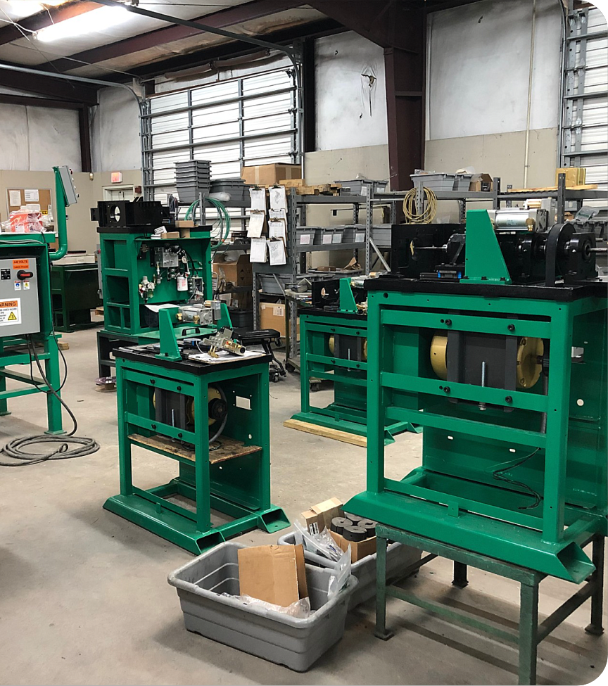
MSI works directly with customers to engineer chamfering solutions for non-standard applications. Our engineering team can review your part drawings, confirm feasibility, recommend tooling configurations, and build custom machines designed specifically for your angle, material, and production requirements. Because our machines are made in the USA with direct factory support, we can respond to specification questions faster and with more precision than distributors or resellers.
Custom angles are a routine part of what we do — not an exception.
Contact us today to request a quote or speak with an expert!